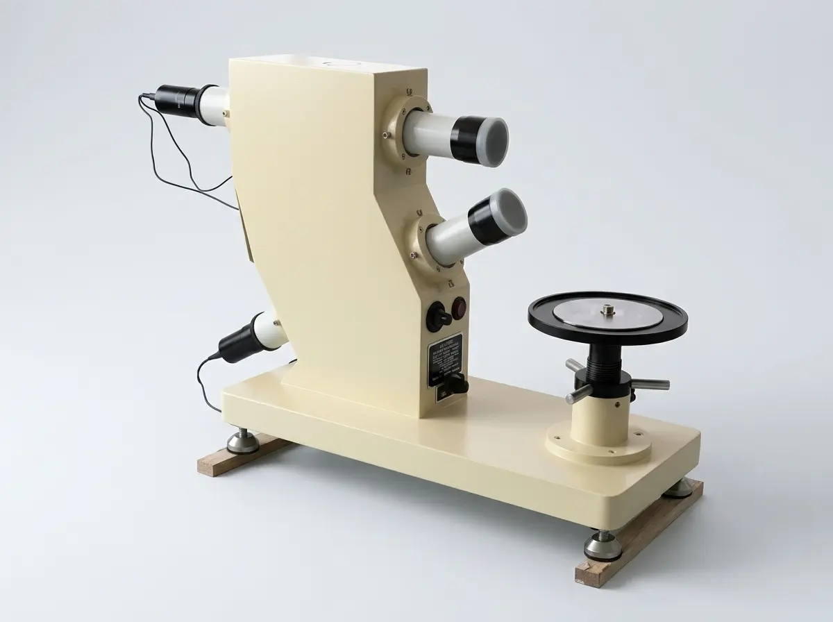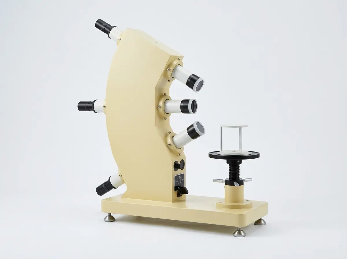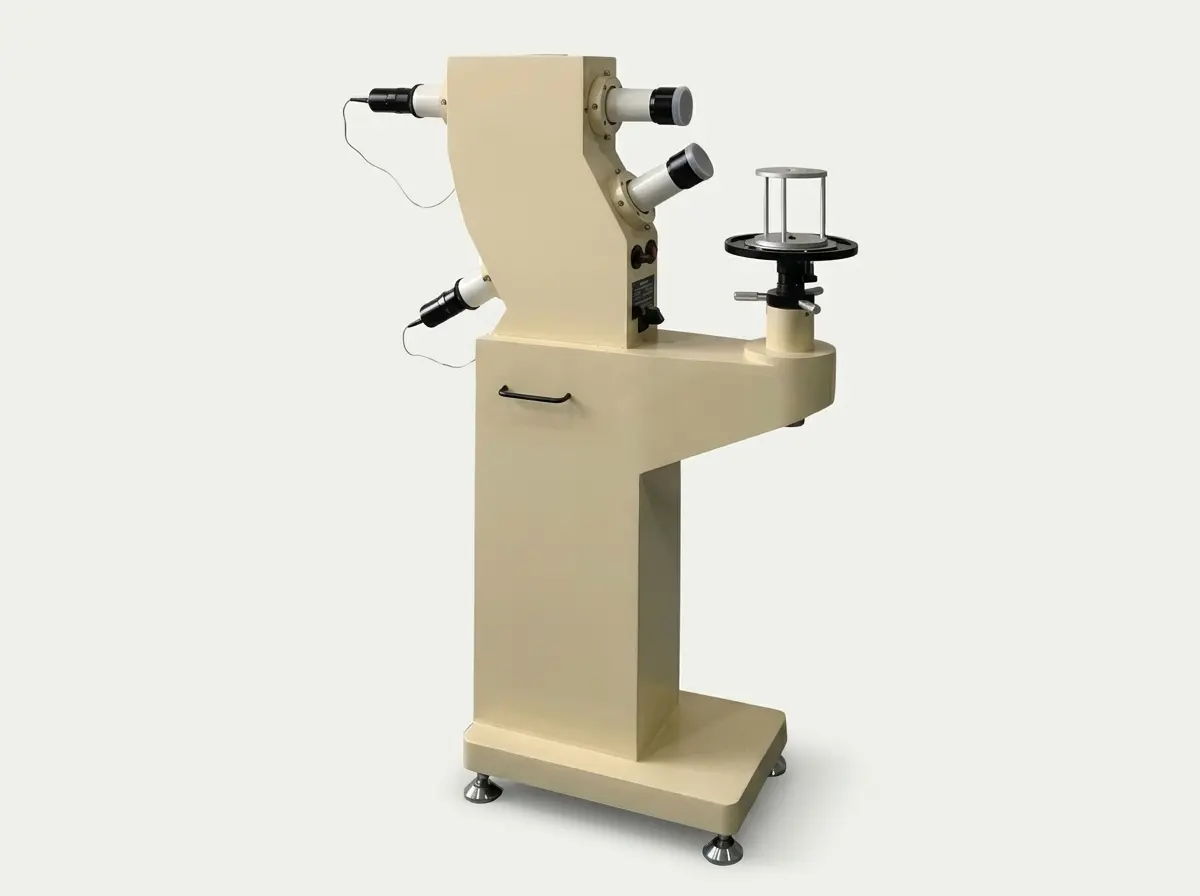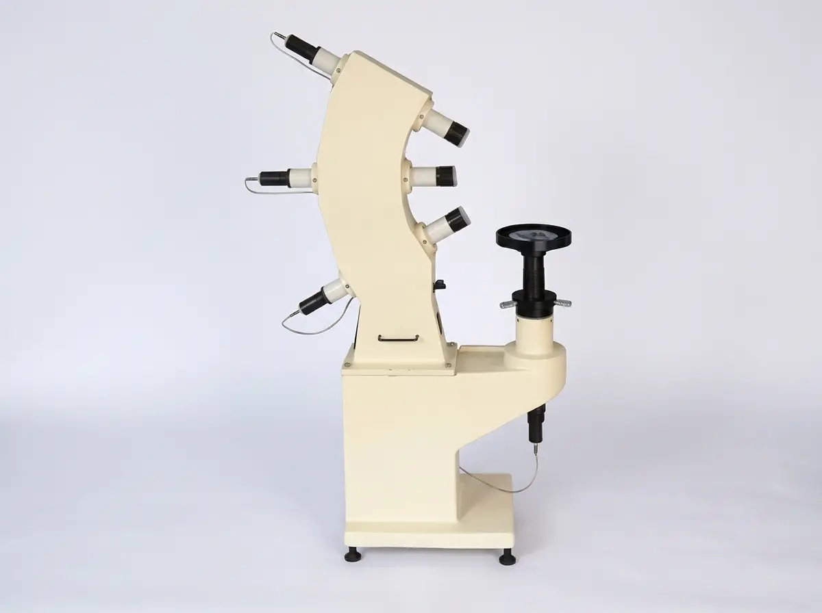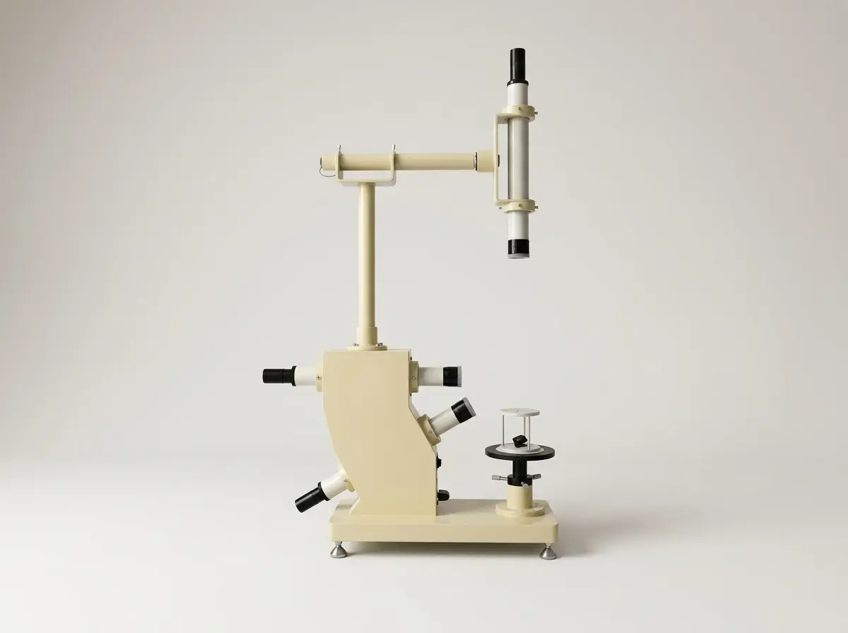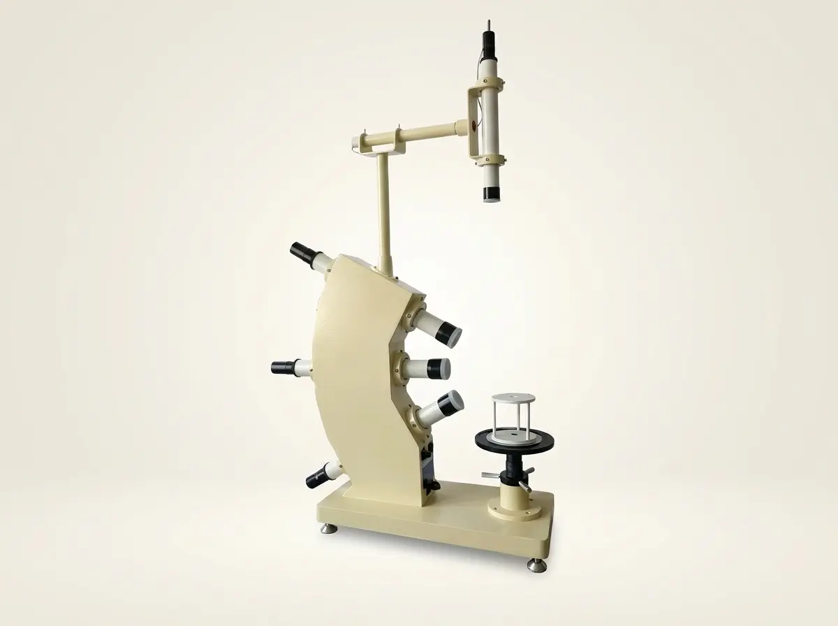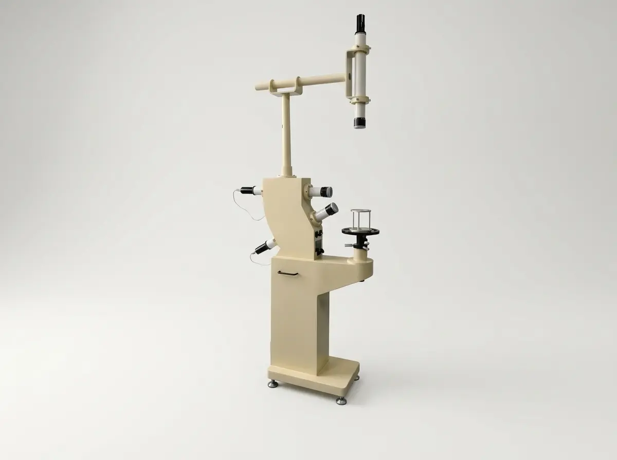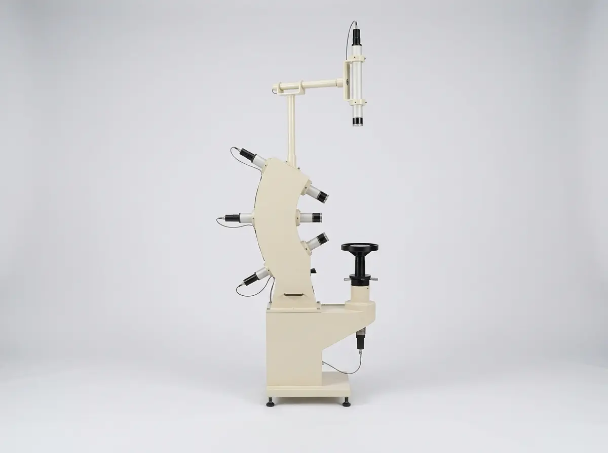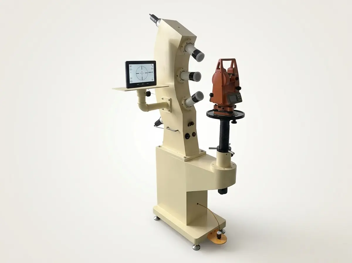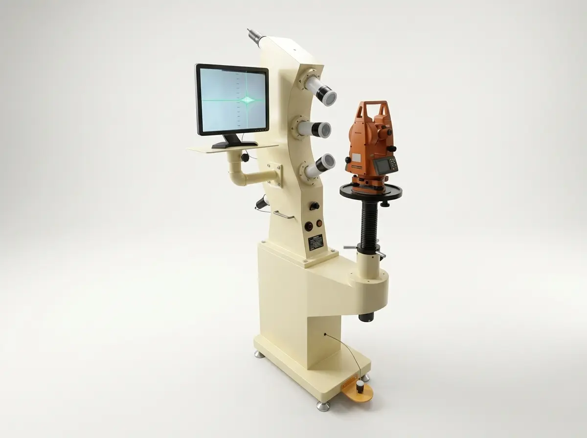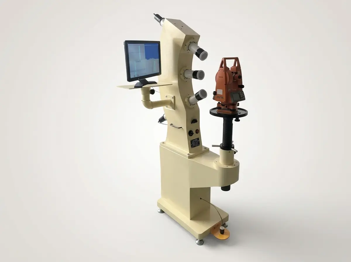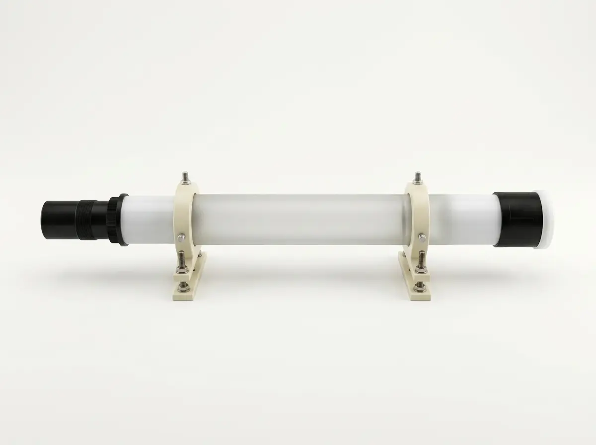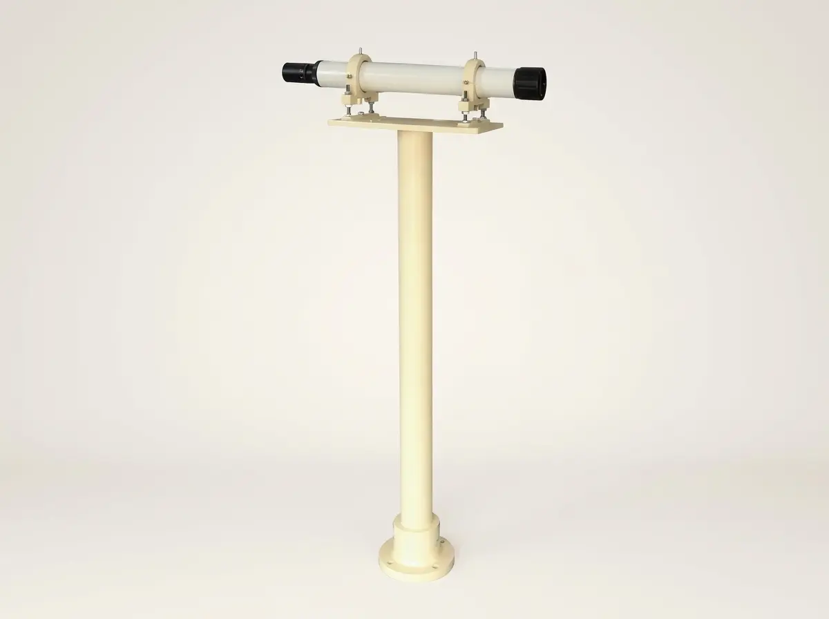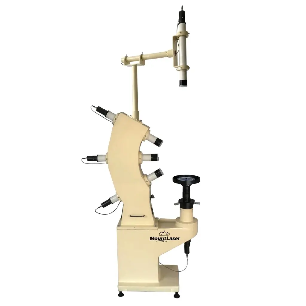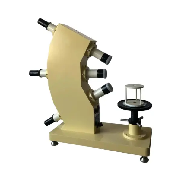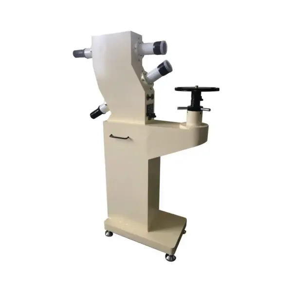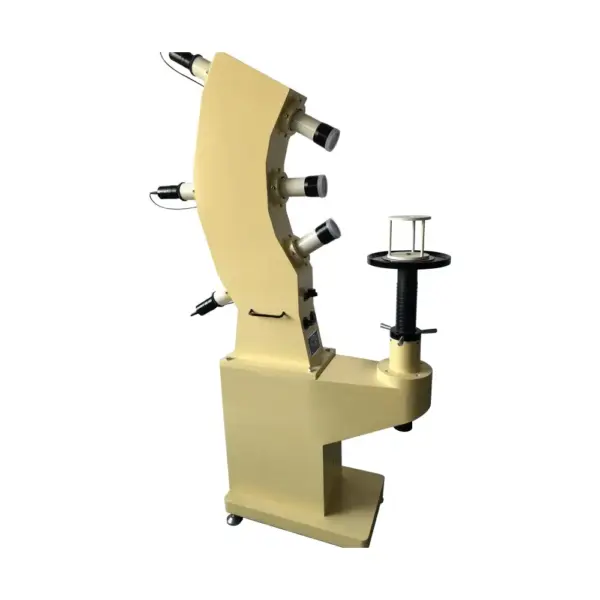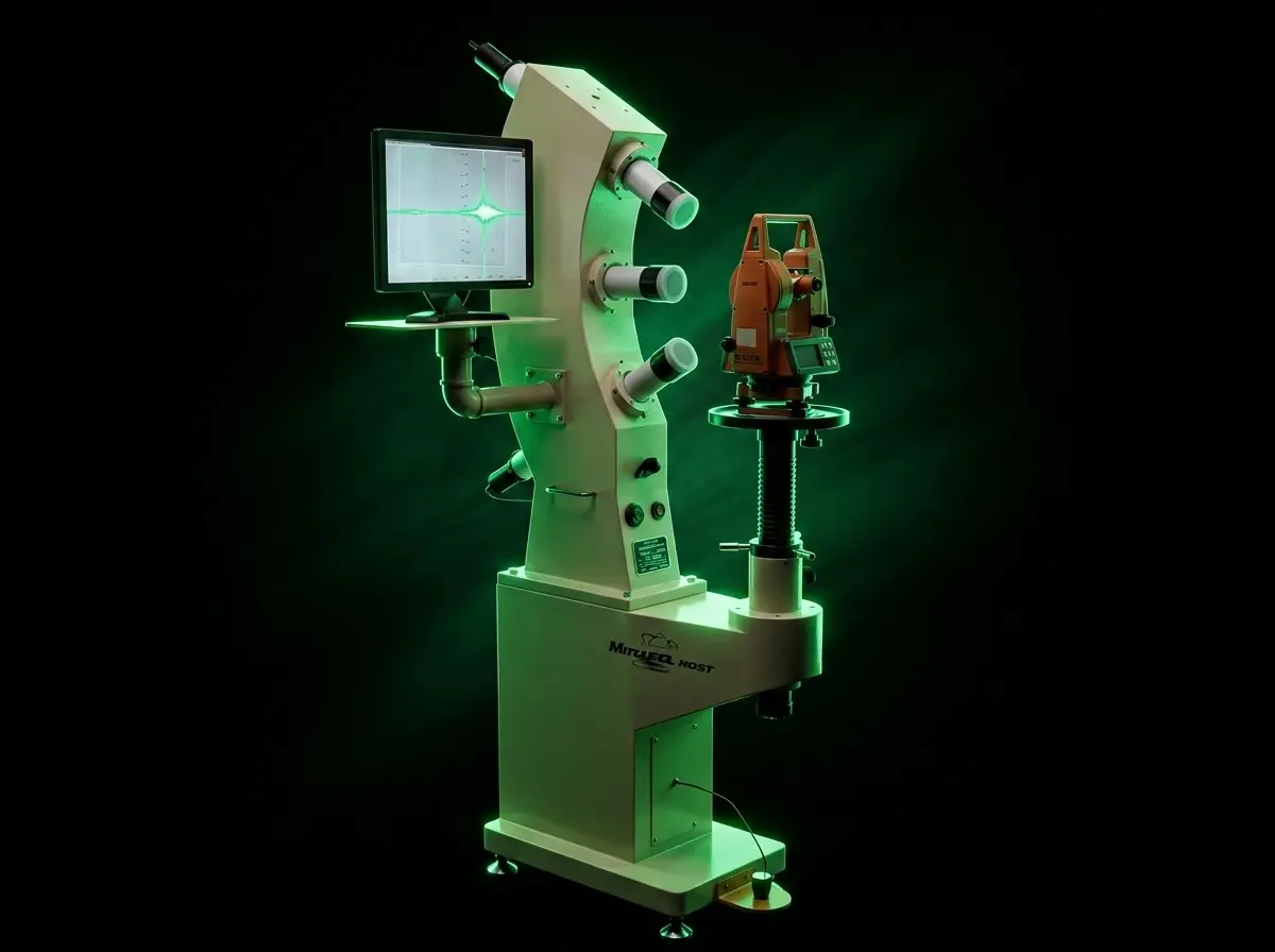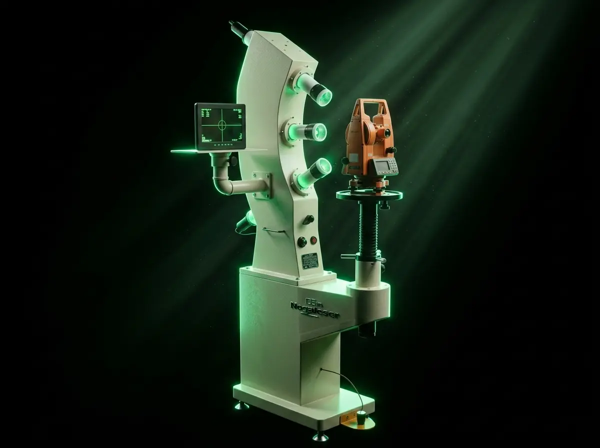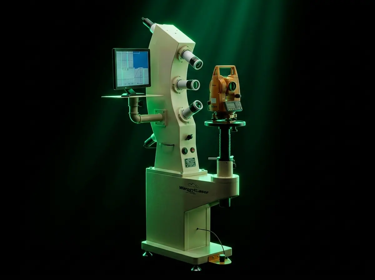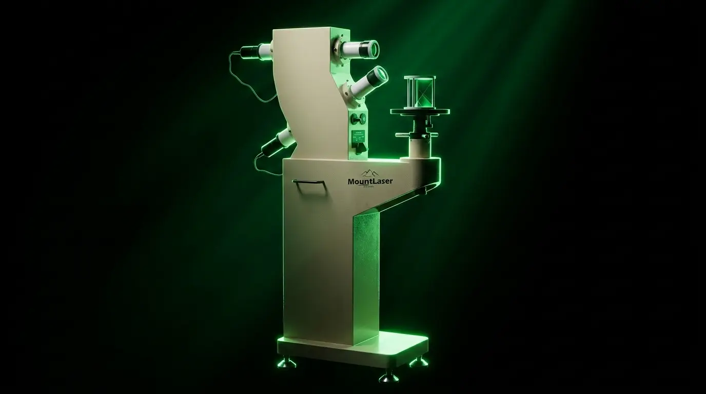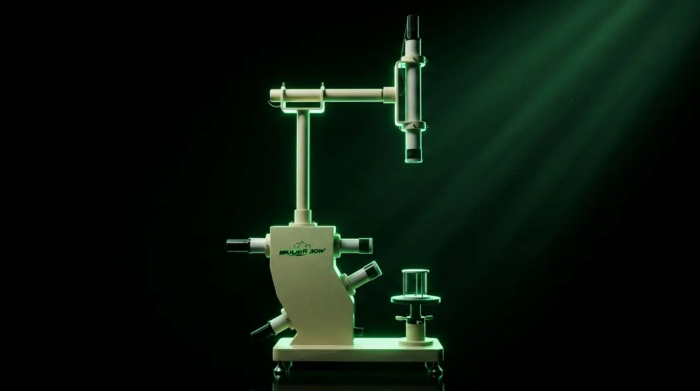














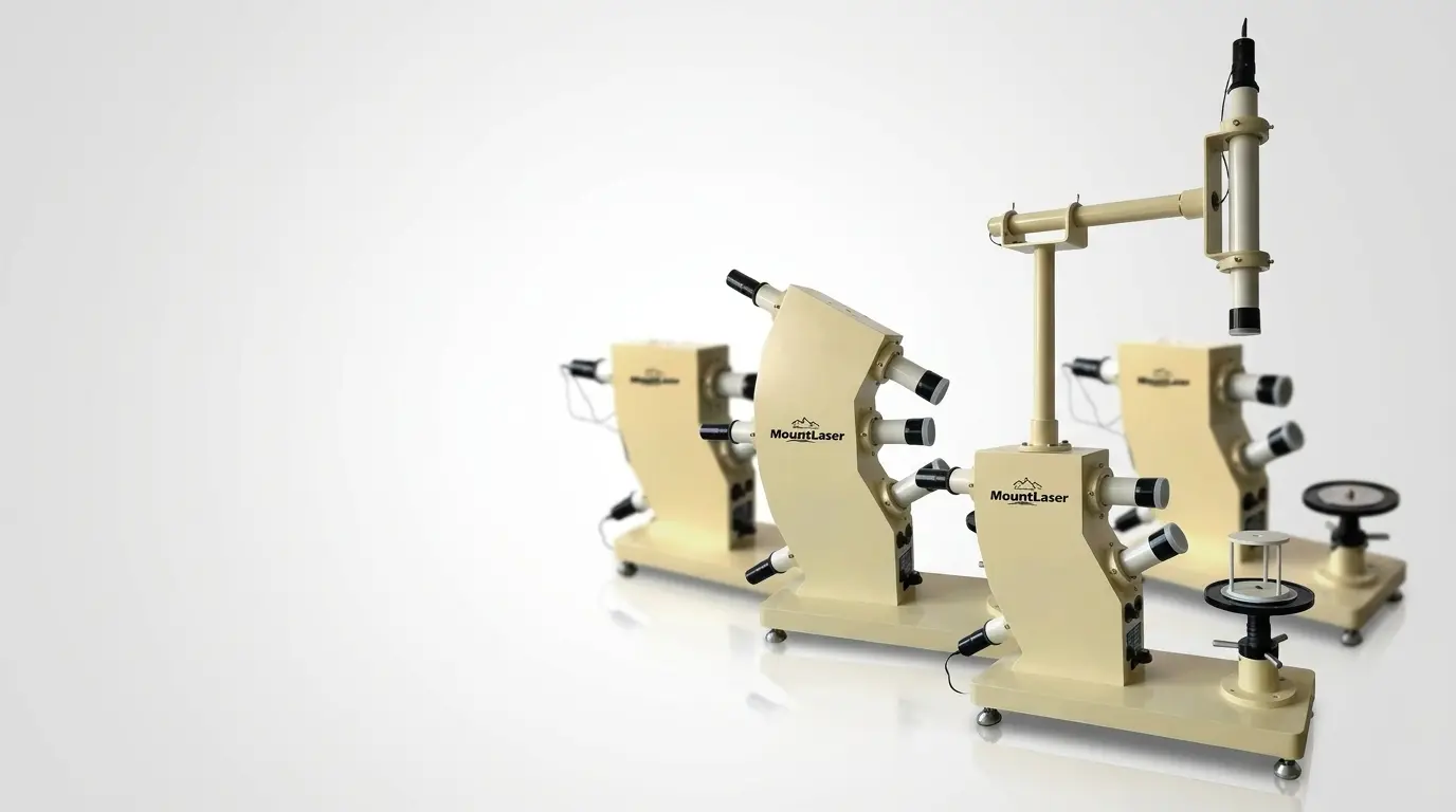
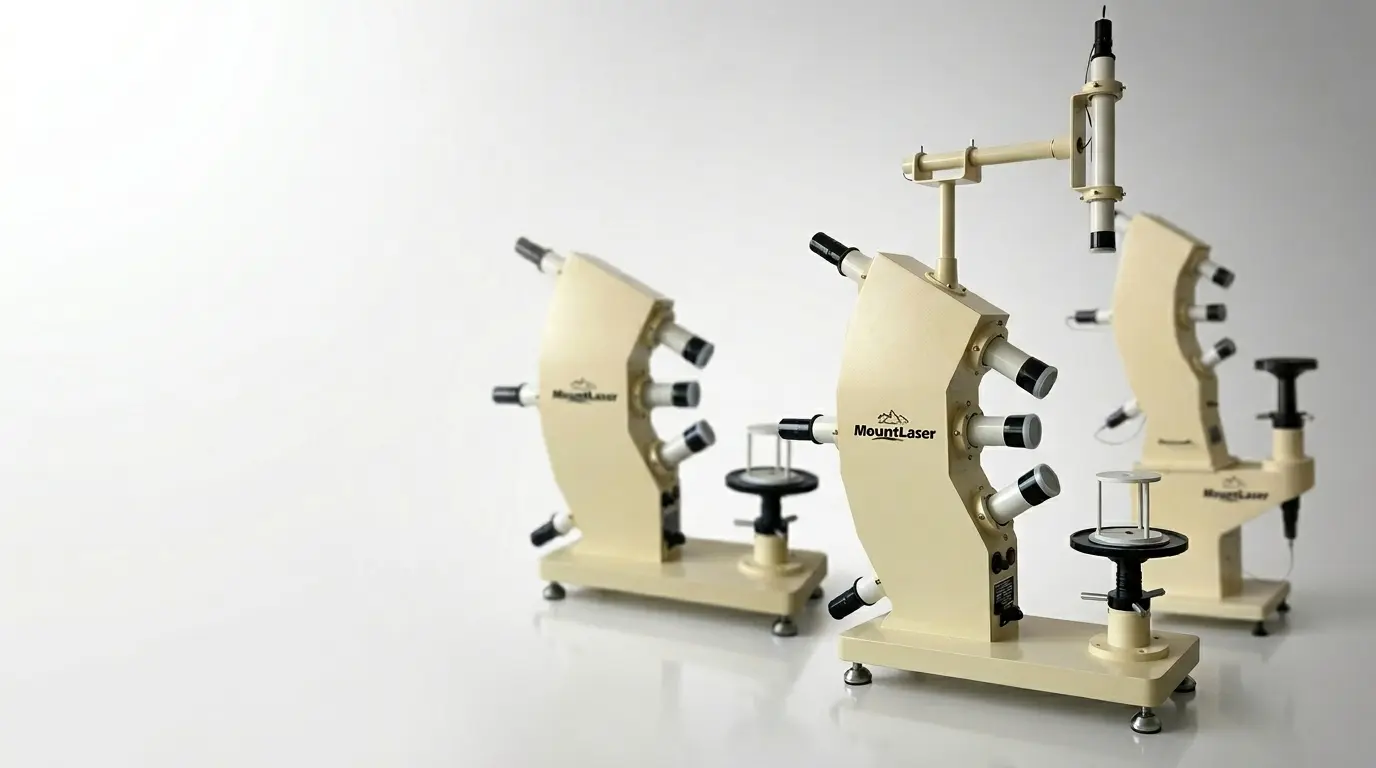
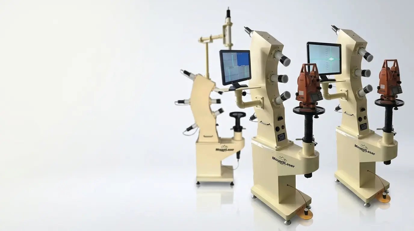
Collimator

Model F550-2P F550-3E F550-2A F550-3 F550-2T F550-3ET F550-2AT F550-3T F550-3S F550-3LS1 F550-3LS3
Instrument Type Auto Level Calibration Bench
Number of Optical Tubes 2 3 2 3 2 3 2 3 3 3 3
Zenith Optical Tube 1 1 1 1
Structure Type Tabletop Tabletop Floor Floor Tabletop Tabletop Floor Floor Floor Floor Floor
Optical Down Plummet No No No Yes No No No Yes Yes Yes Yes
Tray No Lifting Tray (Included)
Application Auto Level Calibration / Adjustment
Display System Small Screen Large Screen Large Screen
Optoelectronic Integrated Tube 1 1 3
Frequency Divider No No Yes

Package

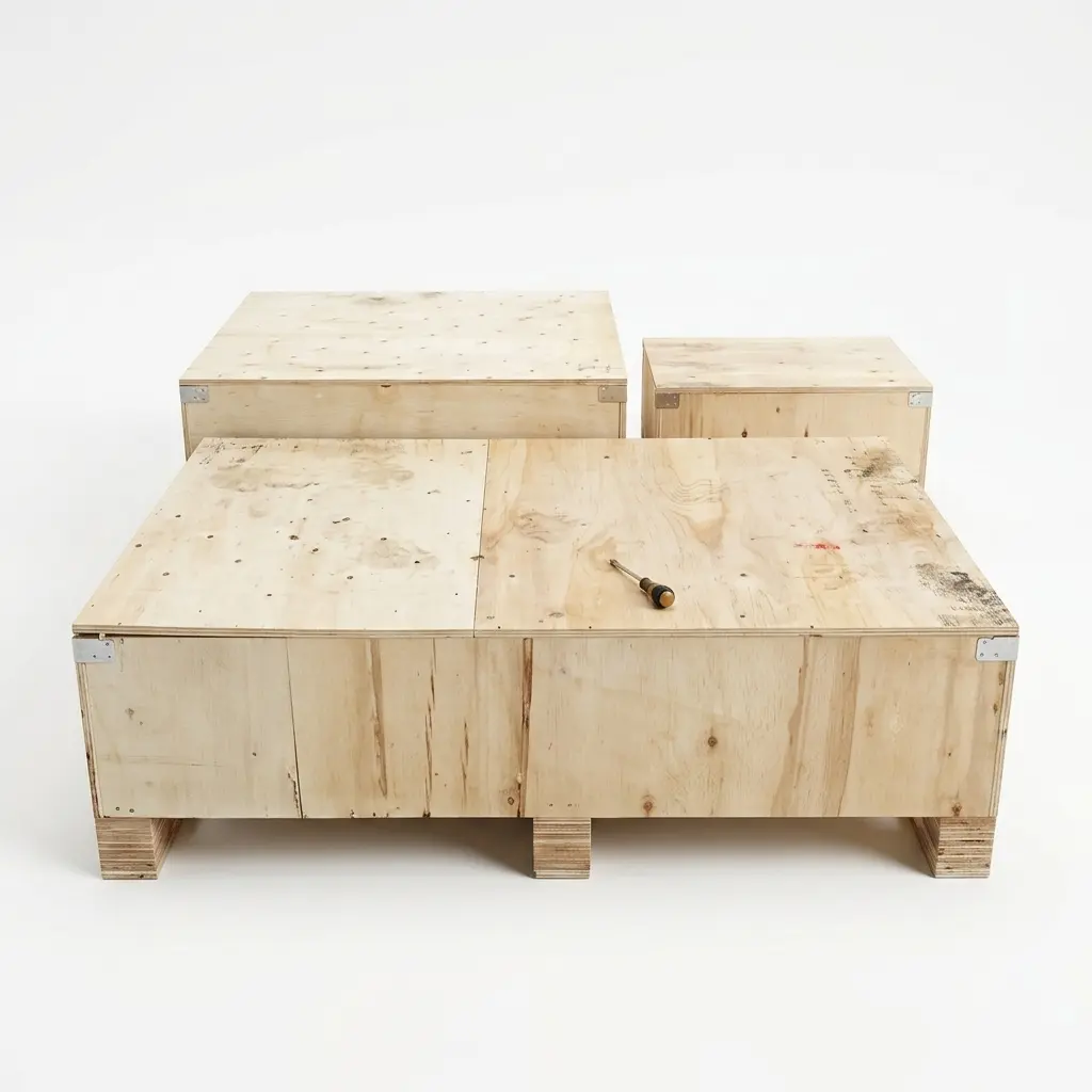
Our calibration bench is packed and protected in a high-strength plywood crate. Unlike traditional solid wood packaging, plywood is an engineered composite material that undergoes high-temperature and high-pressure processing during manufacturing, so it does not require fumigation and complies with international shipping requirements in most countries and regions. The equipment is securely fixed with customized wooden support structures and protected with plastic wrapping and internal cushioning materials to prevent vibration and movement during transportation and handling. Major components, accessories, and the display unit are stored in separate compartments to enhance overall transport safety. This packaging method not only facilitates international shipping and customs clearance, but also provides reliable protection for precision optical calibration equipment, ensuring the system remains in excellent condition after long-distance transportation.

How does it work?

Principle of the Collimator

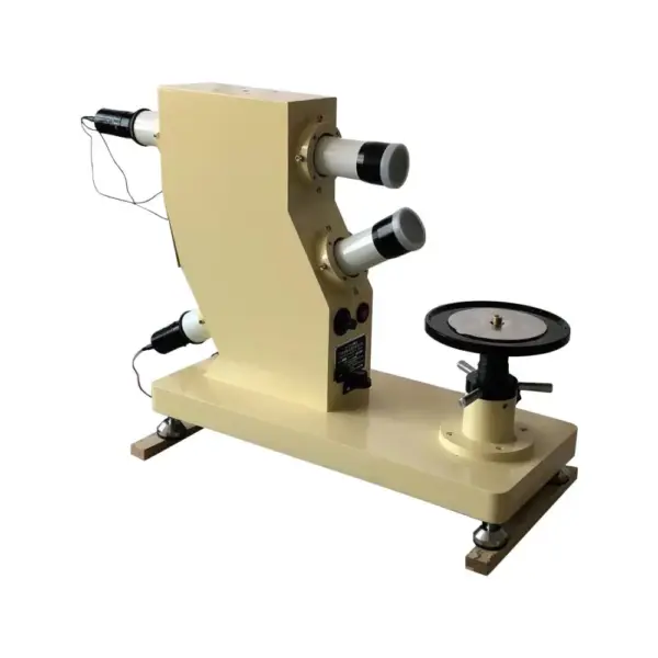
A collimator is an optical device used for the inspection and calibration of surveying instruments. By means of a high-precision optical tube system, it simulates stable and accurate optical targets, providing a standard reference line of sight for instrument testing and adjustment.The collimator is mainly used for the following purposes:Total Station Inspection, Theodolite Calibration, Auto Level Adjustment

Alignment

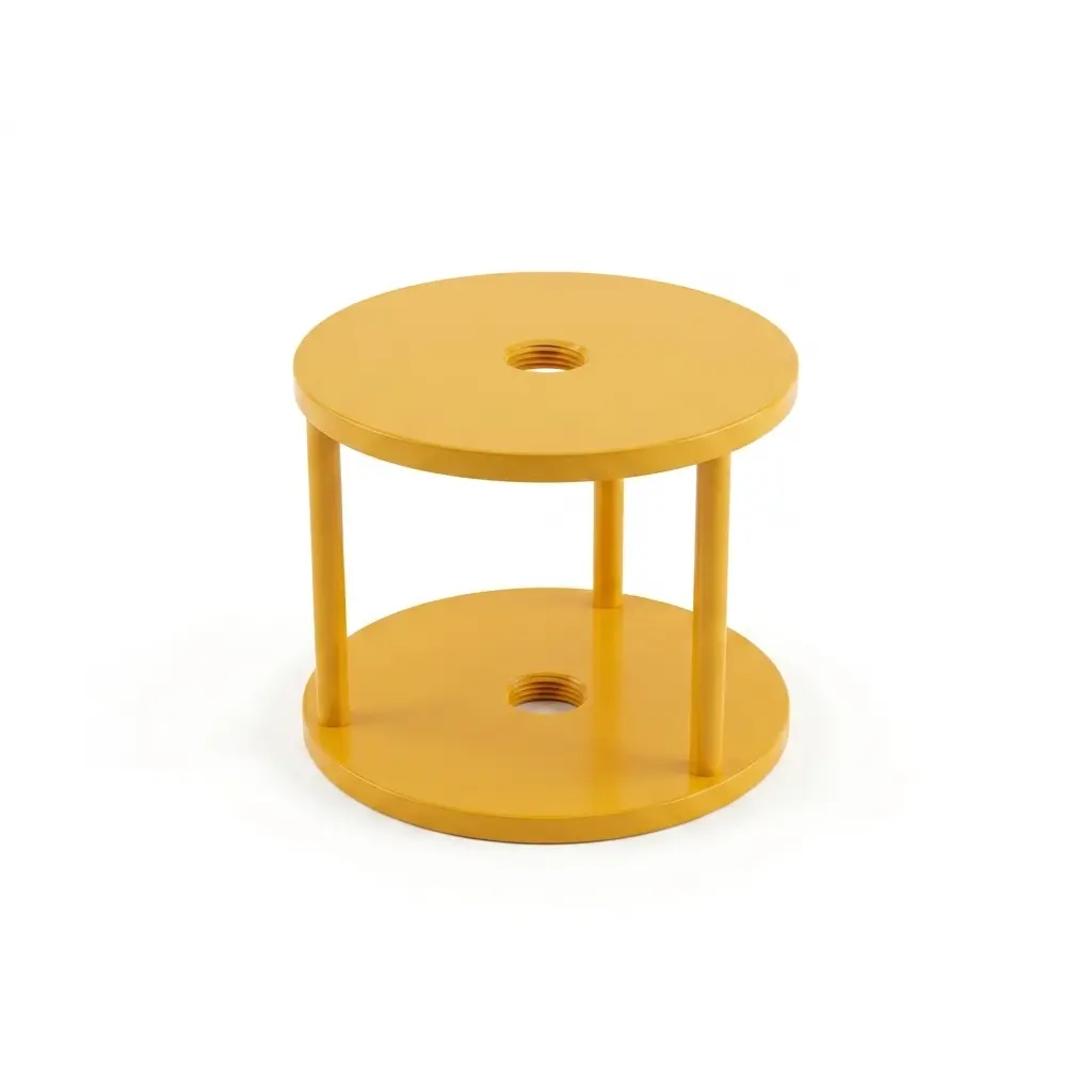
Centering Plate

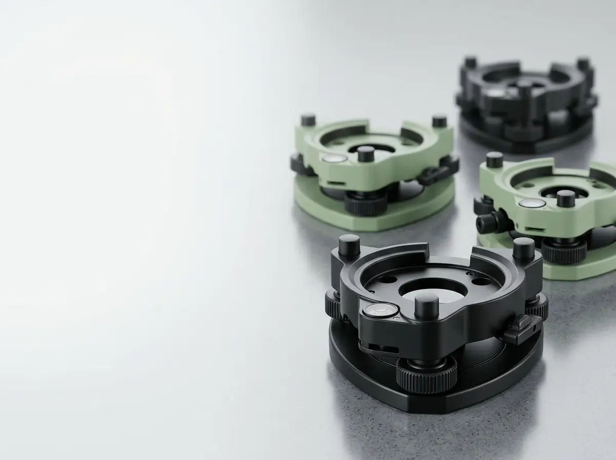
Centering Plate allows stable installation and accurate centering, helping improve calibration efficiency and measurement reliability.

Detection

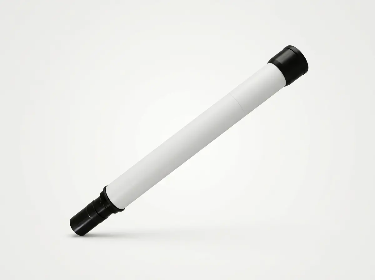
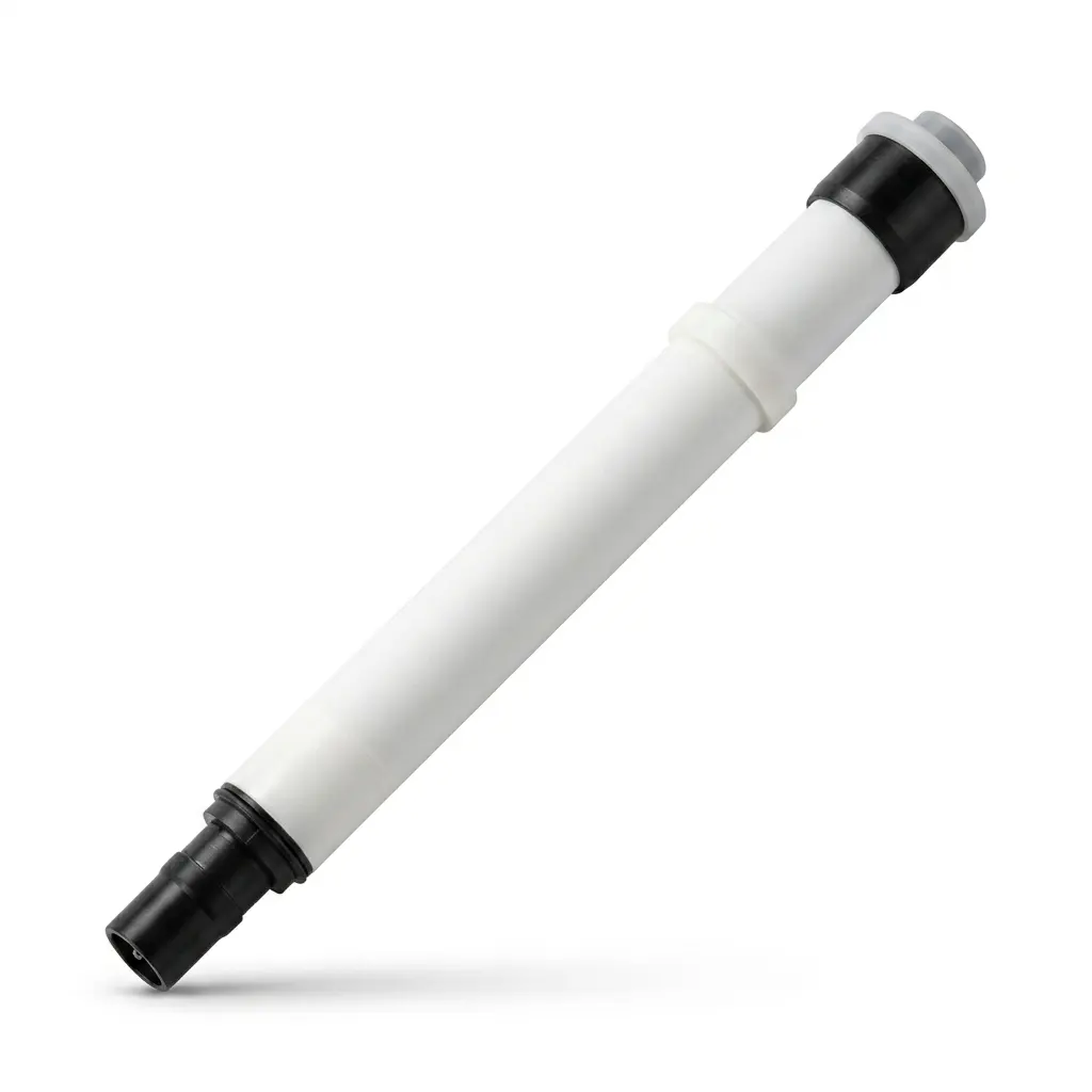
Single-tube

Single-tube enables clear image observation and precise signal acquisition during instrument calibration.

Common Questions & Professional Answers

Using an incorrect prism constant introduces a systematic offset into every distance measurement recorded during the survey. The total station applies the constant as an additive correction to the raw EDM reading, so any error in the constant propagates uniformly across all observations.

⚠ Worked Example

A −30 mm prism was used, but the controller was set to −17.5 mm. The instrument added only −17.5 mm instead of −30 mm, so every recorded distance is 12.5 mm too long. To correct the data, subtract 12.5 mm from all slope distances before recomputing coordinates.

Correction formula:

Δ = PCactual − PCset

If Δ is negative, subtract |Δ| from all distances. If positive, add Δ. The corrected distance is then used to recompute northing, easting, and elevation.

Software-based correction (recommended):

  • 1Open the raw field file in your office software (Trimble Business Center, Leica Geo Office, etc.).
  • 2Locate the prism constant setting in the job properties or raw observation editor.
  • 3Update the constant to the correct value and trigger a full recomputation — all point coordinates will be recalculated automatically.

Best practice: Before each survey session, verify the prism constant by measuring a calibrated baseline with the prism constant set to 0 mm, then comparing the measured distance against the known value. The difference equals the true prism constant.

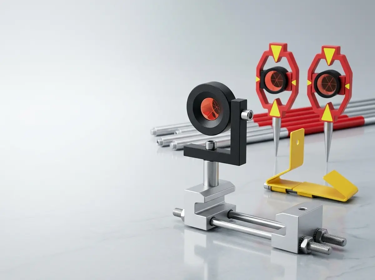
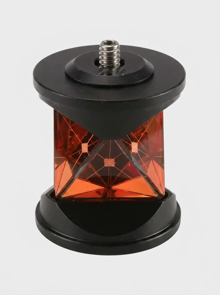
From a purely optical standpoint, yes — standard circular prisms achieve higher centering accuracy than most 360° wide-angle prisms. A 360° prism is an assembly of 6–7 individual corner-cube prisms bonded together; the alignment tolerances of each element accumulate, resulting in a wider pointing error envelope.

Prism Type Centering Accuracy Typical Use Case Verdict
Standard circular prism (e.g., GPR1) ±1.0 mm Control surveys, precise layout Highest Precision
High-precision 360° prism (e.g., GRZ4) ±2.0 mm (any face) Robotic topo, one-man operation Excellent
Standard 360° prism ±2.0 mm (front face)
±5.0 mm (side/rear)
General topographic surveys Good for Topo
Mini 360° prism ±1.5 mm Compact robotic tracking Very Good

In practice, refusing to use a 360° prism for routine topographic surveys is counterproductive. The efficiency gain from omnidirectional tracking with a robotic total station far outweighs the marginal accuracy difference for centimeter-level topo work. However, for high-order control networks, precision deformation monitoring, or industrial alignment, a standard nodal prism is the correct choice.

💡 Pro Tip

When using a standard 360° prism, shooting toward the face marked with the alignment arrow (yellow indicator) reduces pointing error to ±2 mm — approaching high-precision 360° prism performance.

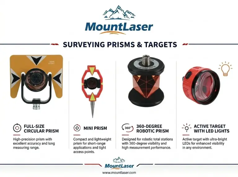
Cross-brand use is technically feasible and widely practiced, particularly in monitoring and industrial surveying. The EDM laser wavelengths of major manufacturers are similar enough that the reflectivity difference between copper-coated and silver-coated prisms is negligible in practice.

The critical requirement is correctly entering the prism constant for the specific prism being used, regardless of brand. The most common source of error when mixing brands is the Leica "Swiss constant" convention:

Brand / System Nominal Constant Absolute Constant Coating
Leica GPR1 (Swiss-style) 0 mm (Swiss) −34.4 mm Copper
Trimble / Topcon standard −30 mm (absolute) −30.0 mm Silver
Japanese-style 360° (e.g., ATP1) −7 mm (absolute) −7.0 mm Silver
Swiss-style 360° (e.g., GRZ101) +30 mm (Swiss) −4.4 mm Mixed
⚠ Critical Warning

If you use a Leica GPR1 (Swiss constant = 0 mm) with a Trimble total station and enter 0 mm as the constant, you will introduce a −34.4 mm systematic error into all distances. Always enter the absolute constant (−34.4 mm) in non-Leica instruments.

MountLaser prisms are manufactured to universal absolute constant standards, making them straightforward to configure on any major brand of total station without proprietary software dependencies.

At distances under 50 m, even a 12.7 mm micro-prism should be reliably acquired by ATR (Automatic Target Recognition). Persistent lock failures at short range almost always point to one of the following causes:

  • 1Uncalibrated ATR collimation. The ATR optical axis may have drifted out of alignment with the telescope crosshair. Run the instrument's built-in collimation calibration procedure (compensator → collimation → trunnion axis tilt → ATR collimation, in that order).
  • 2Contaminated optics. Dust, condensation, or ice on the prism face or the instrument objective lens dramatically reduces the signal-to-noise ratio. Clean both surfaces with a lens cloth before retrying.
  • 3Environmental interference. Highly reflective objects near the prism (chrome bumpers, glass windows, wet surfaces) can confuse the ATR algorithm. Shield the prism or reposition the instrument if possible.
  • 4Passive mode active. Confirm the instrument is set to active tracking mode, not passive mode. In passive mode, the instrument will not emit the tracking signal.
  • 5Beam divergence at long range. At distances beyond 300–500 m, the EDM beam footprint may exceed the prism aperture. Upgrade to a larger-diameter prism (38 mm or 62 mm) for long-range monitoring applications.

Recommended diagnostic sequence: Clean optics → manually aim at prism center → attempt manual lock → if successful, run ATR calibration → retest automatic lock. If the instrument still fails to lock after calibration, contact the manufacturer for a factory service check.

This is a well-documented phenomenon caused by the combination of extreme zenith angle and very short measurement distance. Two independent error mechanisms are at work simultaneously:

1. Cosine error in reflectorless mode: At steep vertical angles, the EDM laser beam strikes the target surface obliquely. The beam footprint becomes an ellipse rather than a circle, and the centroid of the returned signal shifts relative to the crosshair aim point. At 2 m distance and a 45° zenith angle, this shift can easily exceed 5 mm in elevation.

2. Prism orientation error: A 360° or mini-prism that is not precisely pointed toward the instrument introduces a cosine-related ranging error that grows with the angle of incidence. At extreme angles, even a small misalignment of the prism face produces measurable elevation discrepancies.

Measurement Mode Optimal Condition Risk at Steep Angle
Reflectorless (DR) Near-horizontal, flat surface, >4 m distance High error risk
Mini-prism (e.g., 12.7 mm) Prism leveled, near-horizontal angle Moderate risk
Standard prism (25.4 mm+) Prism leveled, near-horizontal angle Lower risk
💡 Best Practice

For critical elevation measurements in confined spaces, set the total station and prism rod at the same height to minimize the vertical angle. When this is not possible, use a prism with a precise circular vial and ensure it is perfectly plumb before recording the observation. For distances under 2 m, a direct steel tape measurement is often more reliable than any EDM mode.

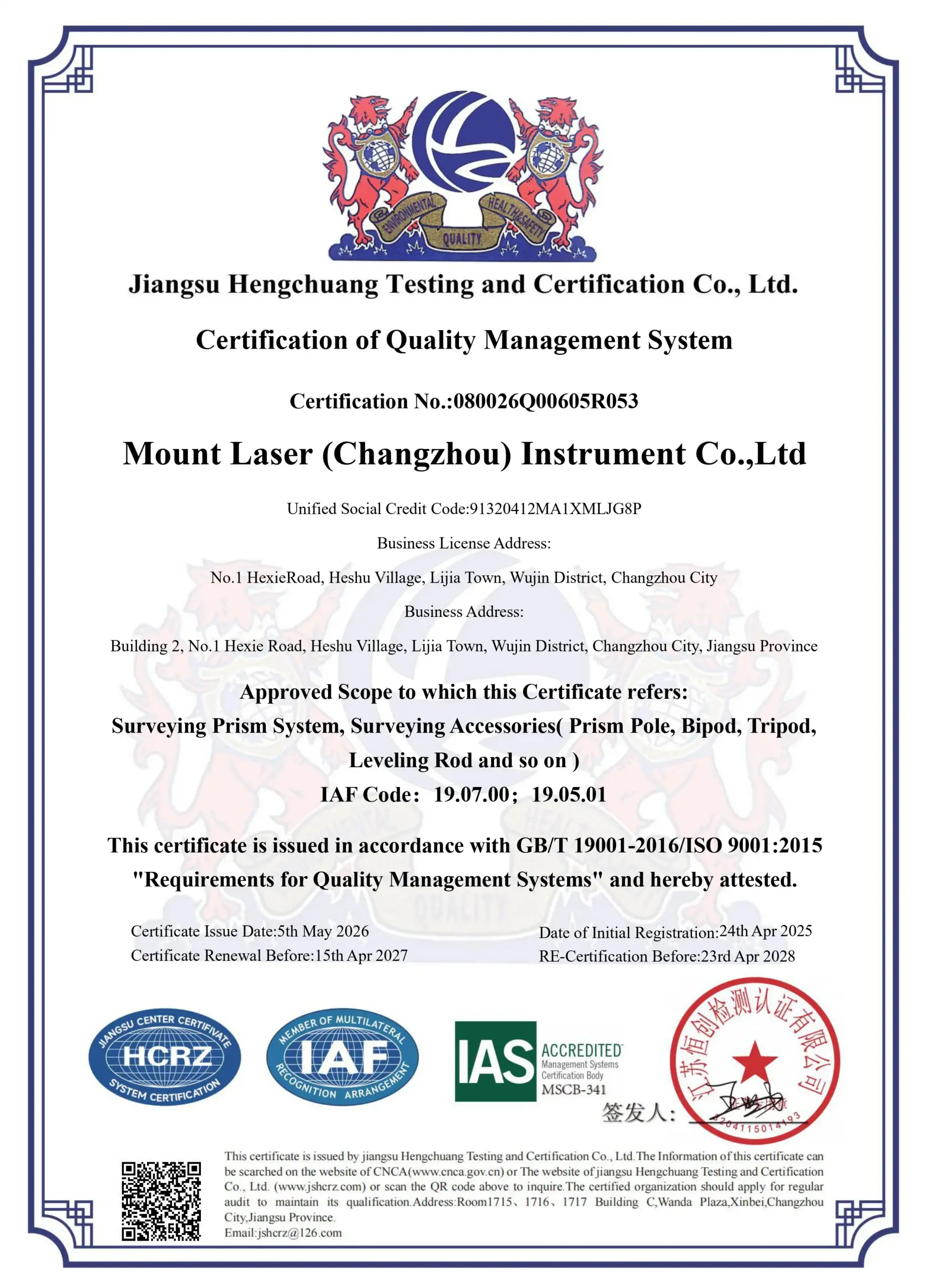
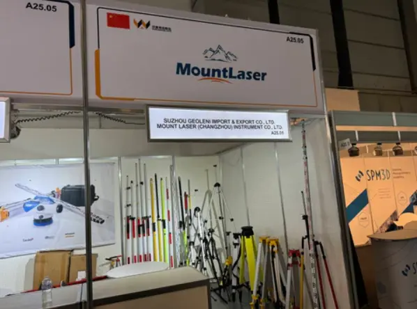
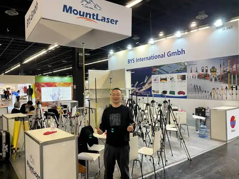
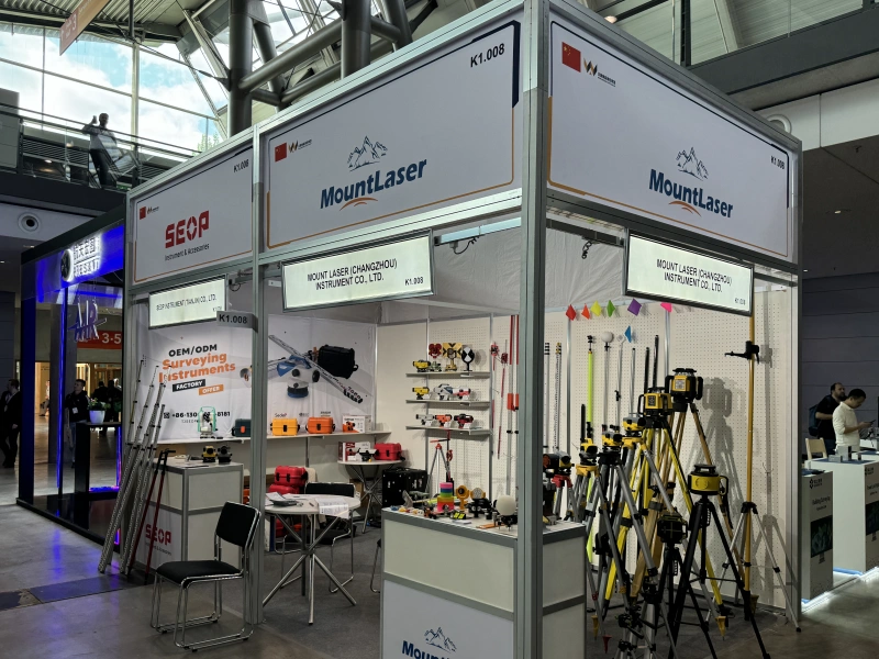
Mount Laser is a leading integrated manufacturer specializing in surveying instruments and accessories, as well as laser levels and accessories. Headquartered in Changzhou, Jiangsu Province, the company operates a 7,500 m² modern manufacturing facility and employs a dedicated team of over 150 skilled professionals. As a comprehensive solution provider, Mount Laser’s product portfolio spans 13 core categories: Auto Levels, Calibration & Testing Instruments, Prisms, Surveying Accessories, Scanner Targets, GNSS, Surveying Poles, Leveling Staffs, Tripods & Bipods, Line Lasers, Rotary Lasers, Laser Level Accessories, and Agent Sales services. Committed to quality and innovation, Mount Laser serves as a trusted partner to surveying and construction professionals worldwide.

MOUNT LASER (CHANGZHOU) INSTRUMENT CO.,LTD

A Chinese Top-3 Manufacturer in surveying accessories!

16 years experience

Modern manufacturing facility
0
skilled professionals
0 +
core categories
0

FAQs

We are a professional manufacturer established in 1999, exporting worldwide with a strong presence in key markets including South America, Oceania, Western Europe, South Asia, and the Middle East, while continuously expanding into emerging markets such as North America, Eastern Europe, and Africa. With over two decades of industry experience, we deeply understand the diverse needs of customers across different regions and are committed to providing reliable measurement solutions to our global partners.

Mount Laser is a leading manufacturer serving the surveying accessories, construction, GPS, and GNSS industries. Our competitive advantage lies in our integrated production capabilities.

We understand that international buyers often need to test the market first. For standard products, we offer flexible MOQs—small trial orders are welcome. For deep customization projects, MOQ depends on the complexity (e.g., mold development, PCB changes). We are happy to discuss a roadmap that starts with small orders and scales up as your business grows.

Absolutely. As a manufacturer with strong R&D capabilities, we specialize in deep customization services. We can tailor products according to your specific requirements.

We are a manufacturer with in-house trading capabilities (industry & trade integrated). Headquartered in Changzhou, Jiangsu Province, we operate a 7,500 m² modern facility with over 150 skilled professionals. Unlike pure trading companies, we control the entire production process—from R&D and mold design to assembly and quality control—ensuring competitive pricing, stable supply, and full customization flexibility for our global clients.

Feedback

5/5

Dr. Mariel Senry

neurologist

13 years experience

4.9/5

Dr. Rachel Haldims

Family medicine

20 years experience

4.8/5

Dr. Damian Pix

orthopedic surgeon

16 years experience

4.5/5

Dr. Shi Yon

Cardiovascular Specialist

11 years experience