













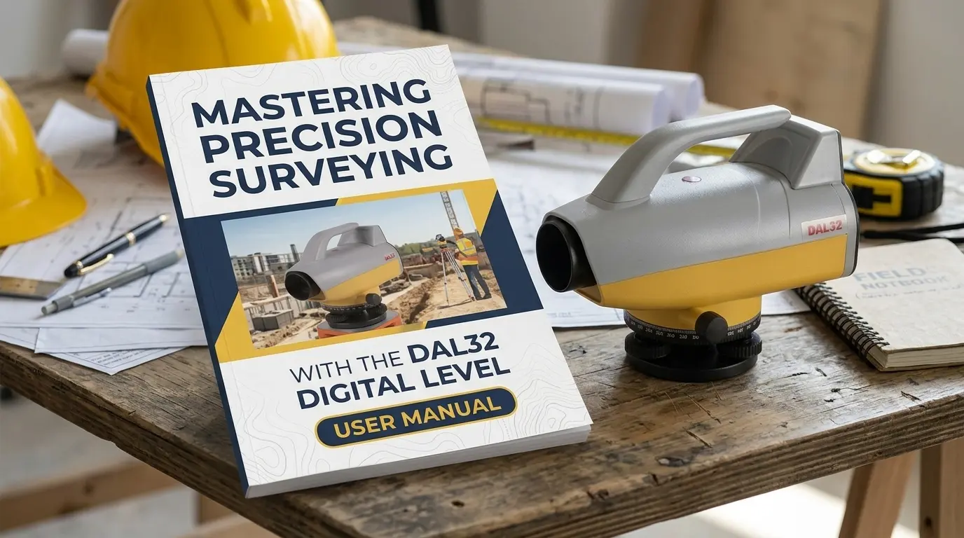
Operating professional surveying instruments requires strict adherence to standardized setup and operational workflows, and following a reliable DAL32 digital level user manual ensures optimal measurement accuracy on every job site. Electronic digital levels combine advanced optical sighting with digital sensor technology to streamline elevation measurements, minimize operator reading errors, and deliver repeatable high-precision results for construction and geodetic applications.
Step 1: Instrument Setup and Leveling
The foundation of accurate leveling lies in proper mechanical setup. Begin by securely connecting and tightening the electronic digital level onto a stable tripod. Once mounted, adjust the tribrach footscrews systematically to center the circular bubble in the bullseye level, guaranteeing a stable horizontal reference plane before powering on the system.
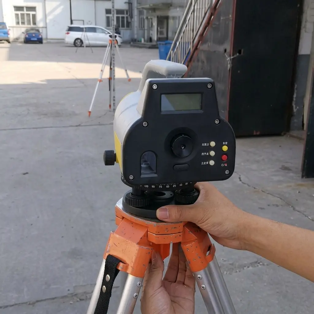
Power on the instrument by pressing the red power button located on the control panel. The digital display will initialize, preparing the internal sensor arrays and capacitive touch interface for operation.
Step 2: Optical Sighting and Focusing
Accurate target acquisition requires proper optical alignment using the onboard sighting mechanisms:
- Rough Sighting: Use the rough sighting device positioned on top of the instrument to roughly align the telescope crosshairs with the target leveling staff.
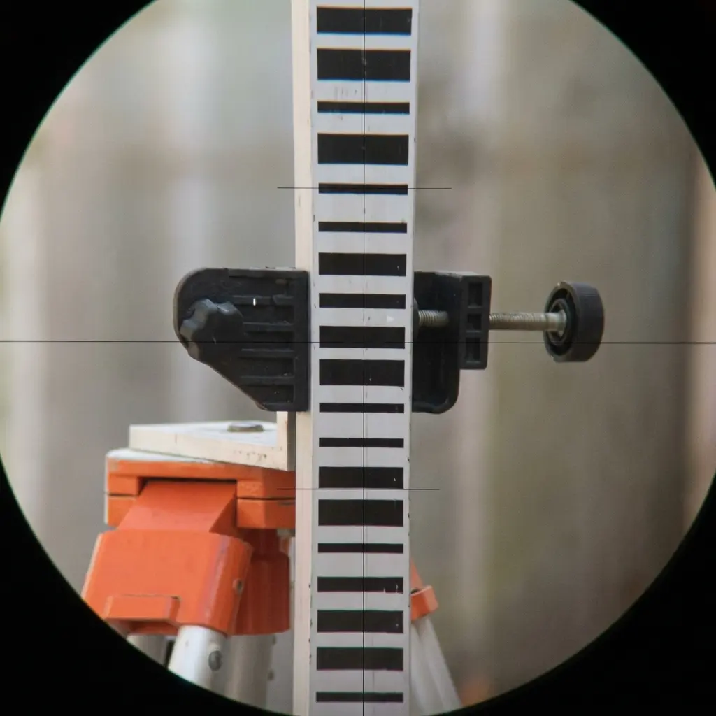
- Diopter Adjustment: Rotate the eyepiece and adjust the diopter ring until the black crosshairs appear sharp and clear against your field of view.
- Image Focusing: Rotate the focusing knob until the target leveling staff image is sharp and distortion-free.
- Fine Adjustment: Use the fine adjustment knob to precisely position the vertical crosshair in the exact center of the leveling staff.
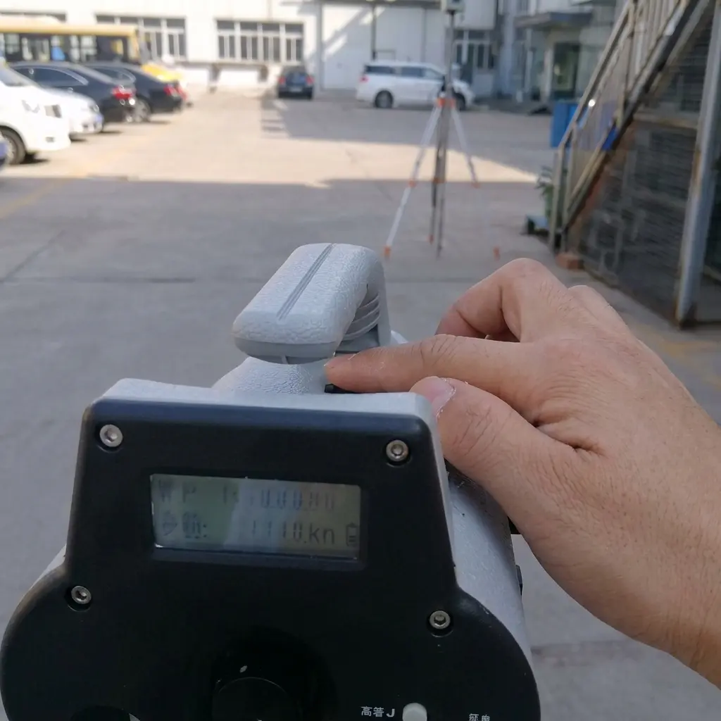
Step 3: Executing Measurements and Height Differences
Modern electronic digital levels feature responsive capacitive touch buttons designed to eliminate mechanical vibration during data capture. Pressing the touch-sensitive measurement button on top of the instrument—or the dedicated function button on the lower left of the panel—triggers an instant reading.
To compute height differences between multiple backsight and foresight locations:
- Sight and measure Staff 1 to capture the initial baseline reading.
- Rotate the instrument to site Staff 2, then press the measurement button to obtain Staff 2 height.
- Press the height difference button to display readings for Staff 1, Staff 2, and their calculated elevation delta instantly on the LCD screen.
| Operational Step | Primary Action | Key Benefit |
|---|---|---|
| Instrument Mounting | Secure to tripod and center circular bubble via footscrews | Establishes a stable reference horizontal plane |
| Target Sighting | Rough aim, adjust diopter, focus image, and center crosshair | Ensures parallax-free optical clarity |
| Data Measurement | Use touch-sensitive top button or lower-left function key | Prevents instrument shaking for superior accuracy |
| Height Calculation | Measure staff 1 and staff 2, then press height difference button | Automates elevation delta calculation |
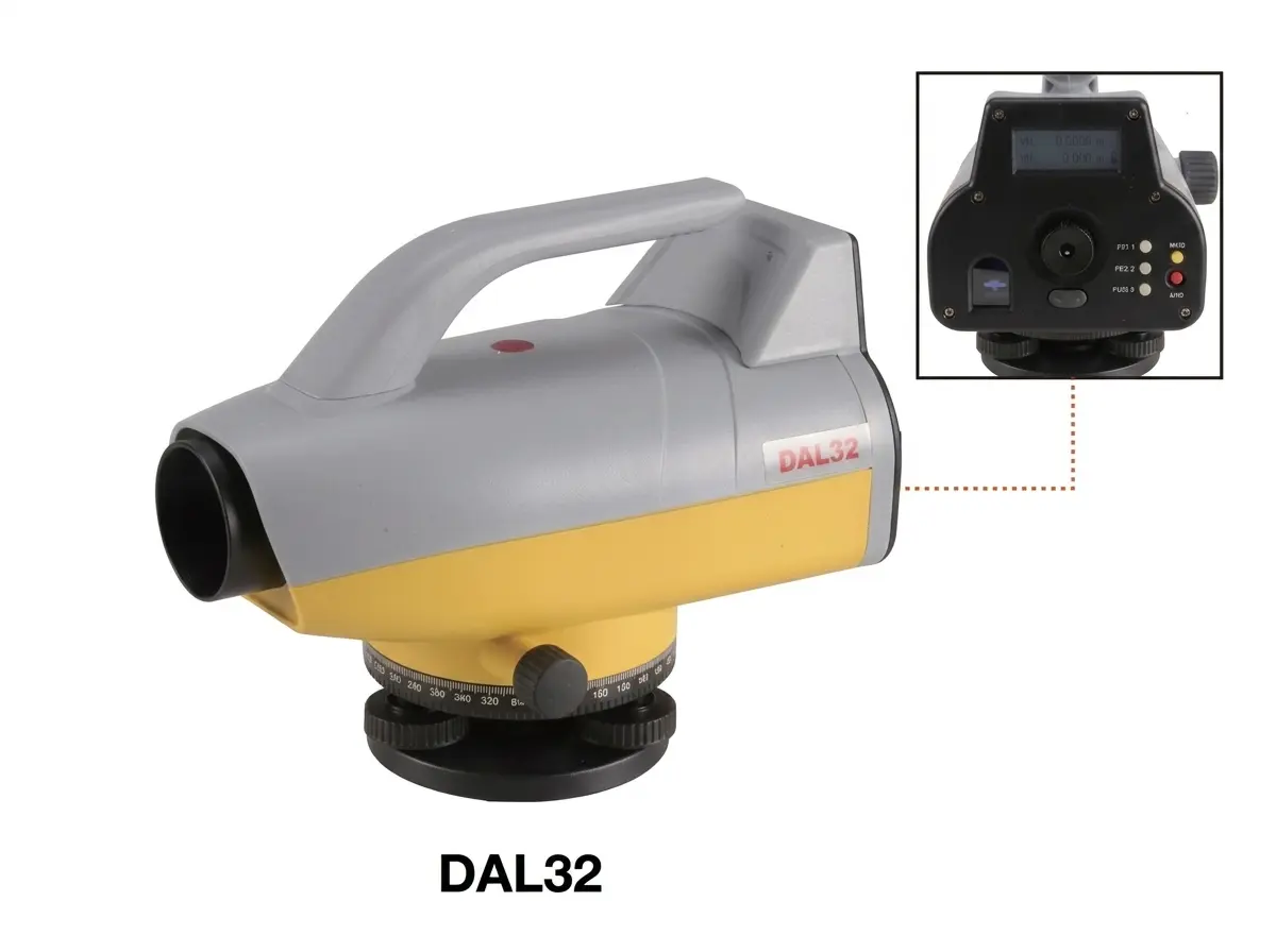
High-accuracy electronic digital level engineered for reliable leveling, robust environmental resistance, and intuitive field operation.
View Specifications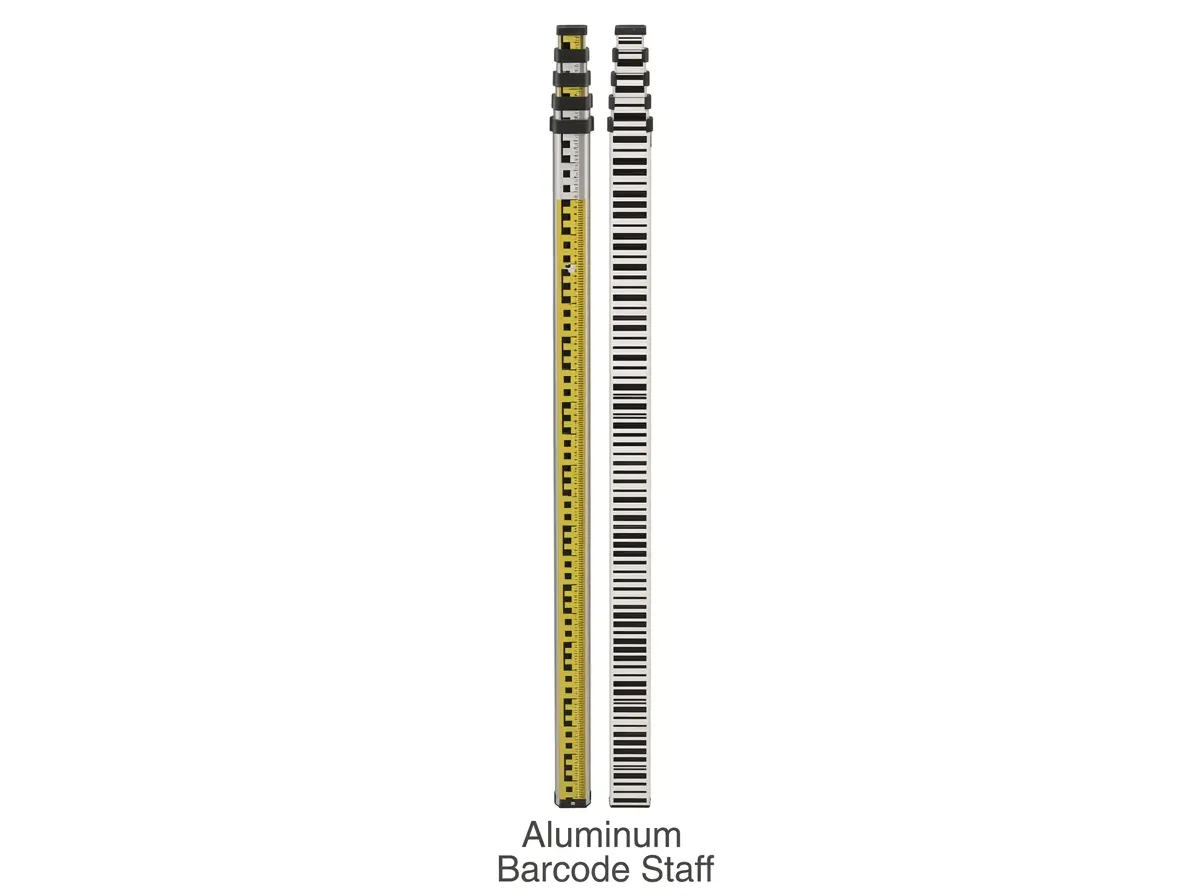
Durable fiberglass and aluminum leveling staves optimized for barcode reading and electronic digital level measurement workflows.
Explore AccessoriesMountlaser Global Manufacturing Excellence
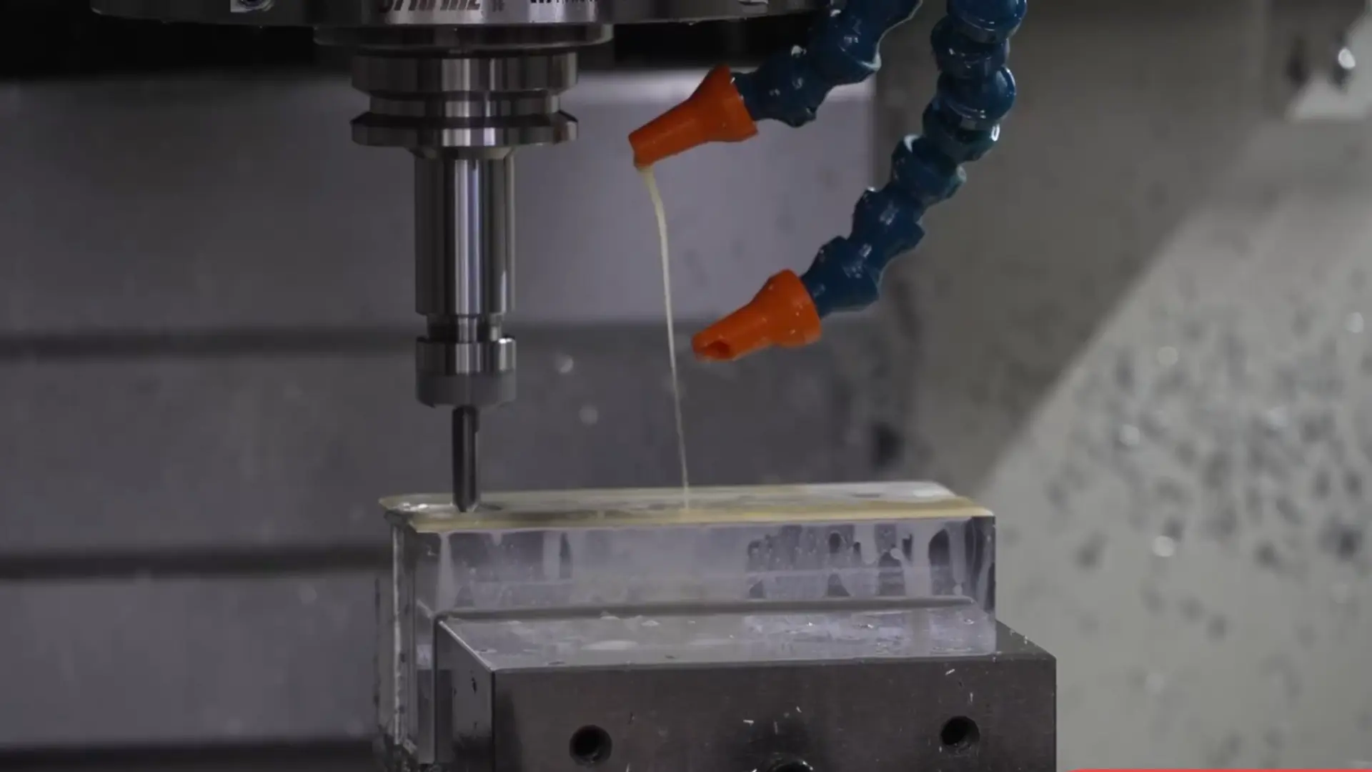
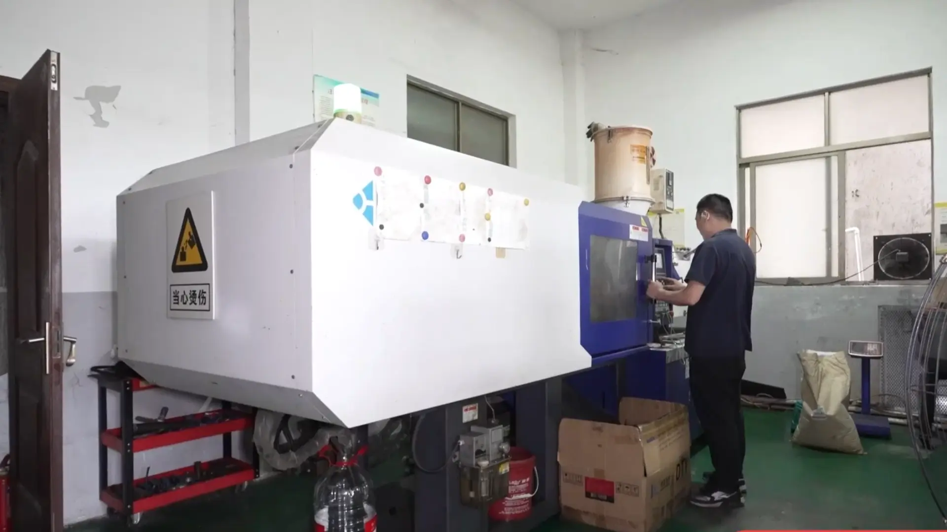
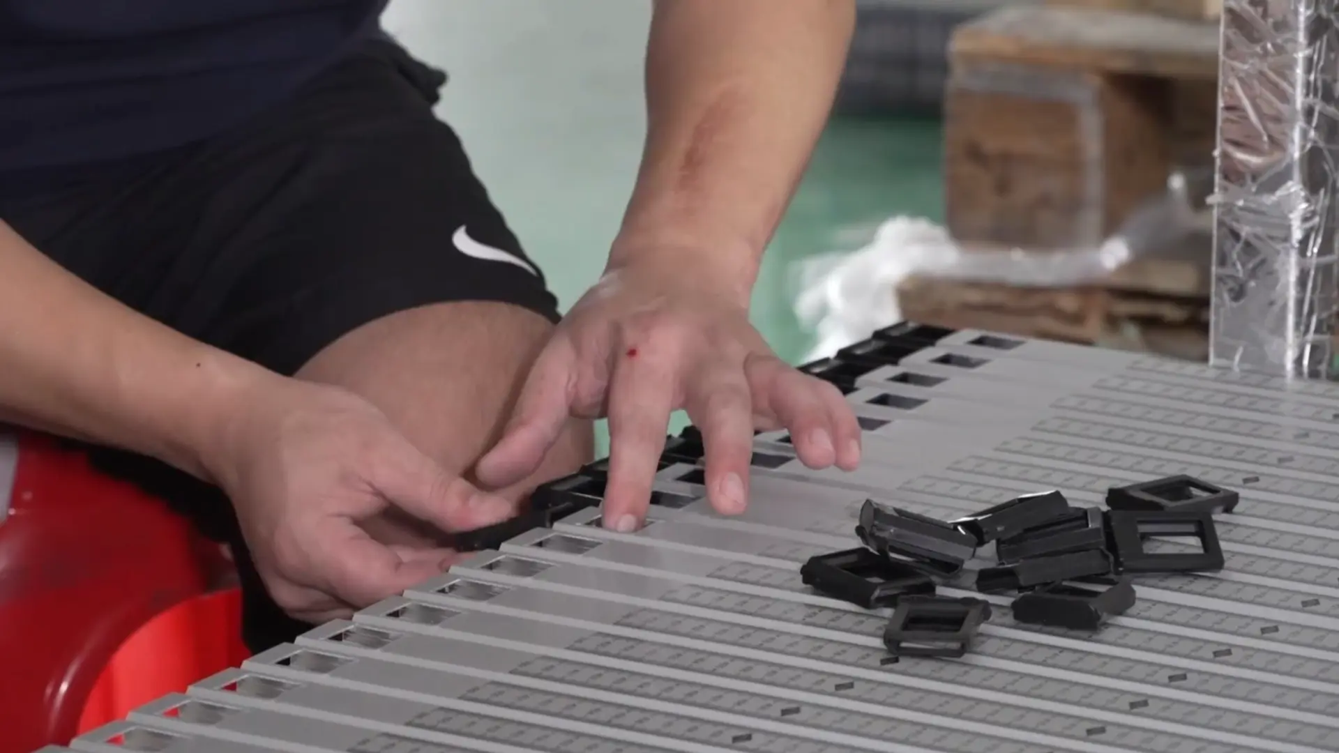
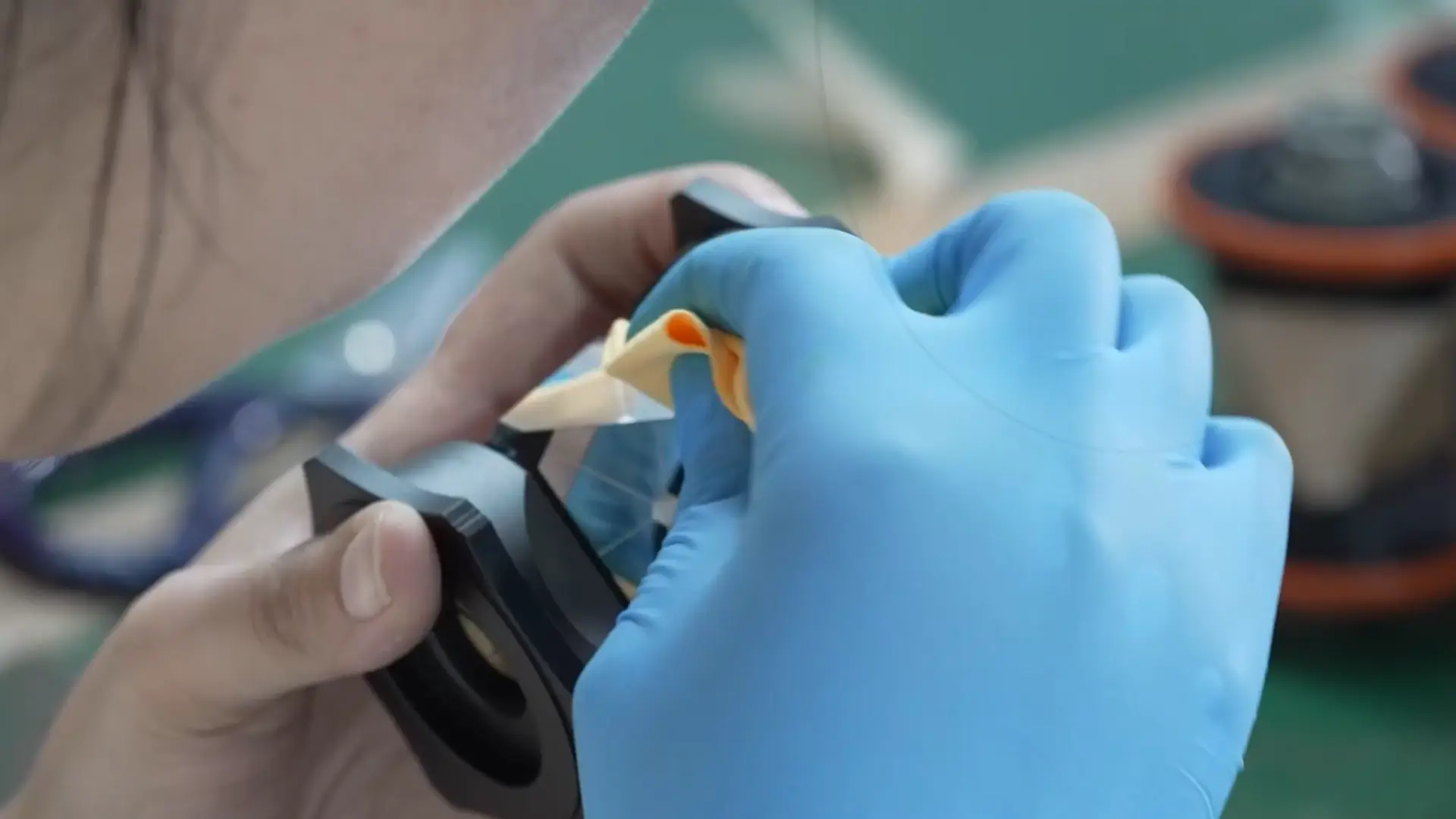
Mountlaser (Mount Laser Changzhou Instrument Co., Ltd.) is supported by robust in-house manufacturing capabilities in Changzhou, China. From raw material to finished optical accessory, every component moves through a controlled process designed for repeatable accuracy and dependable field performance.
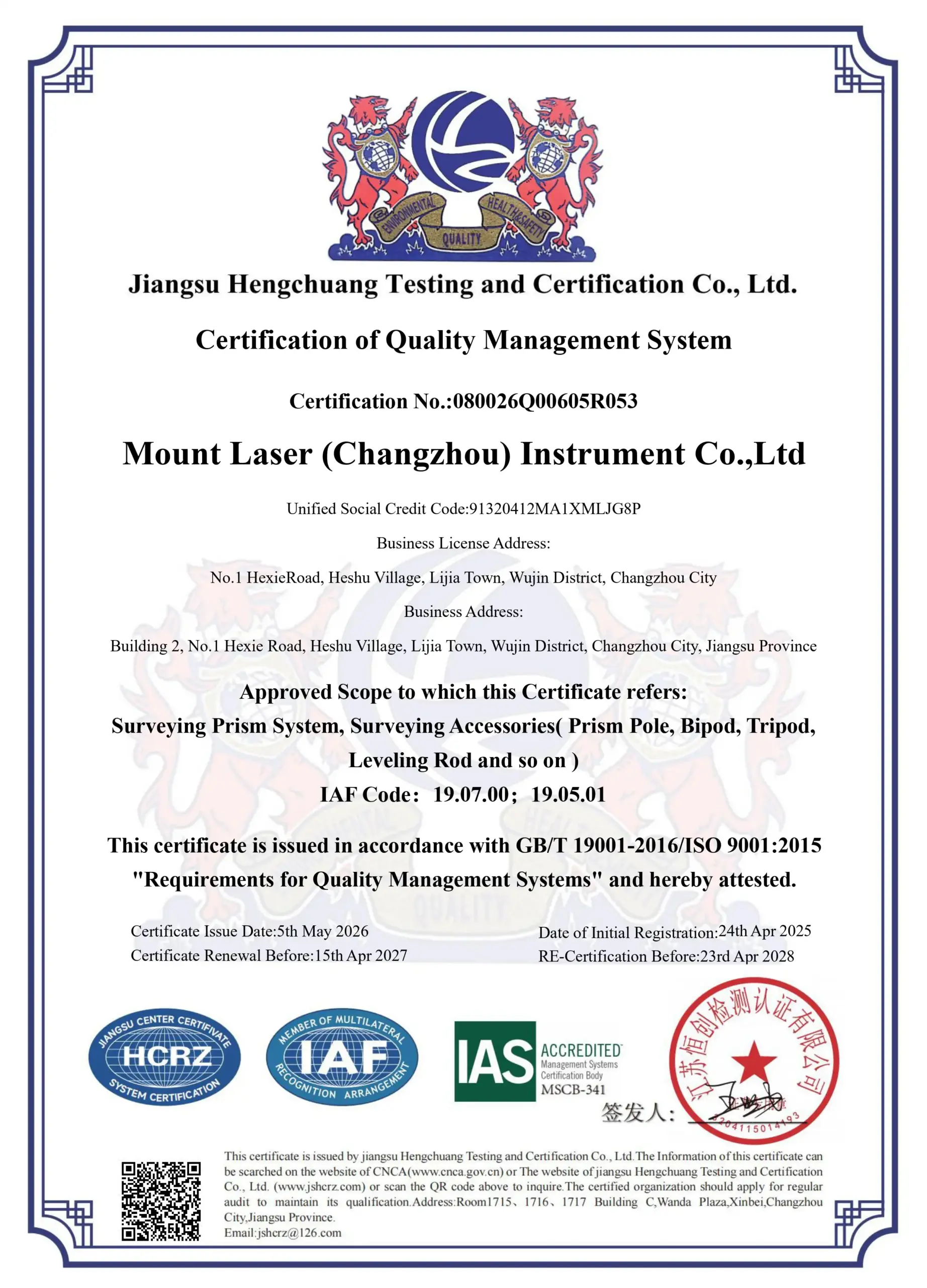
Our manufacturing capabilities can be tailored to meet specific customer requirements, including customized specifications, dimensions, materials, finishes, and functional configurations. Our quality management system is certified to ISO 9001:2025, and applicable products and processes conform to the requirements within the scope of our certification.
ISO 9001 Certification
CNC Workshop
Injection Molding Workshop
Assembly Workshop
Prism Assembly
Prism Accuracy
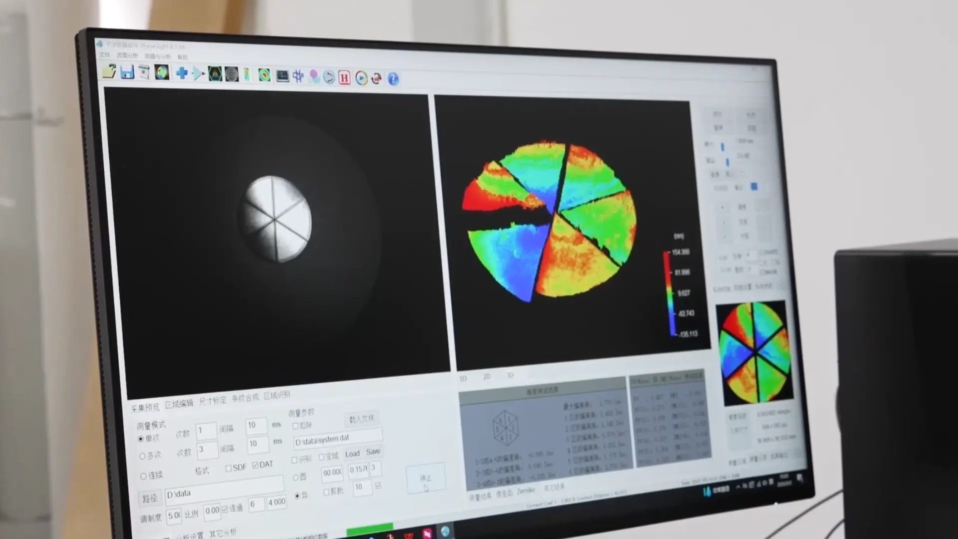
Laser Scale Marking
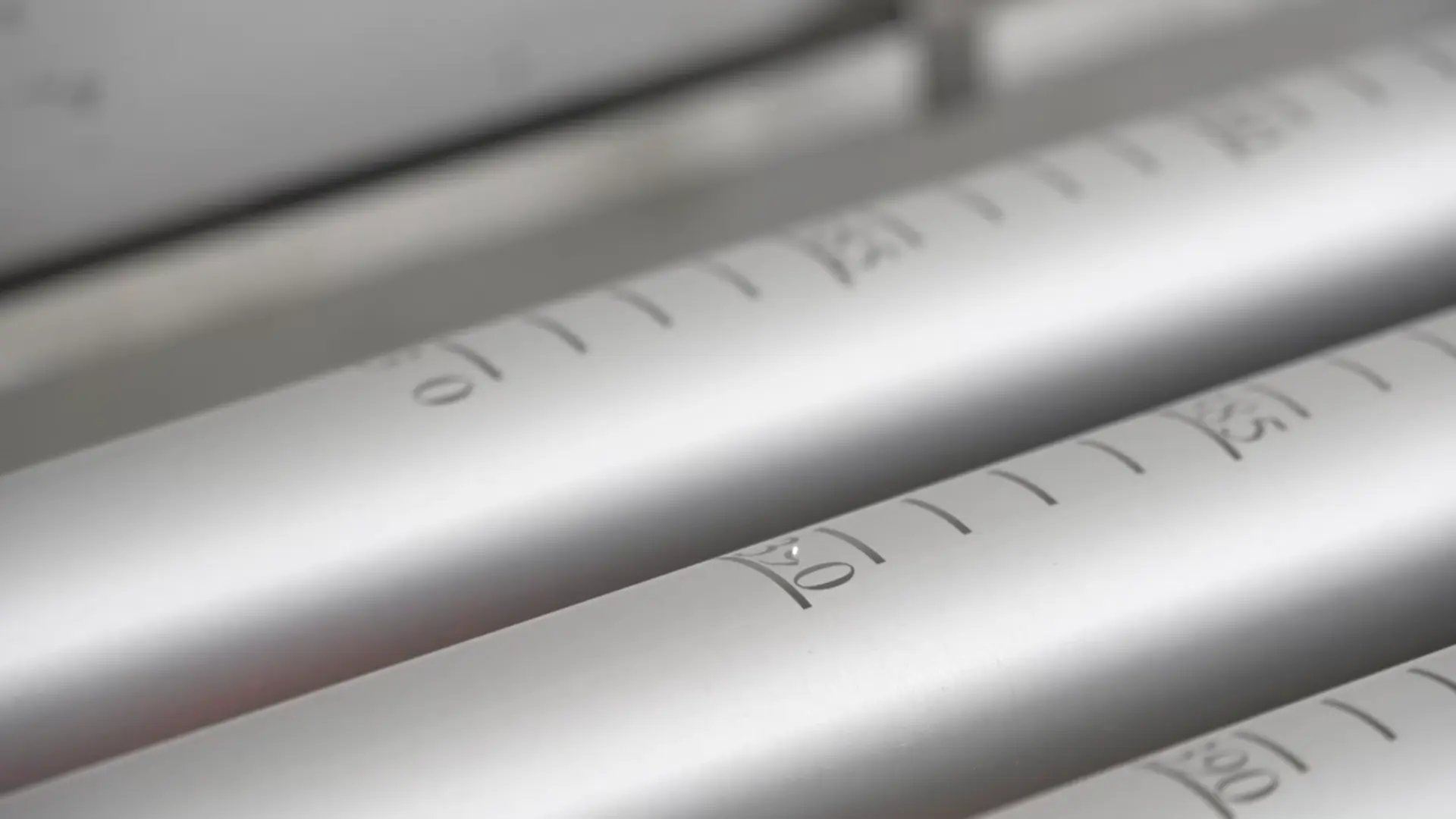
Rod Scale Printing
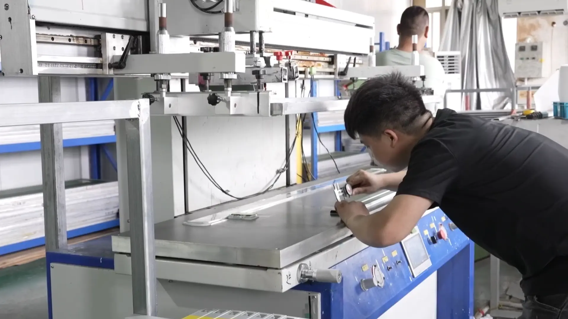
Mountlaser combines factory-direct manufacturing, product development, quality control, and responsive B2B cooperation to support distributors, surveying equipment companies, and professional users in global markets.
Reviewing this detailed DAL32 digital level user manual empowers survey technicians and engineering teams to maximize instrument lifespan and achieve flawless elevation accuracy. For further inquiries or custom B2B partnership opportunities with Mountlaser, reach out via our direct contact channels near the conclusion of this guide.